

How To Clean Plate And Frame Heat Exchanger
A plate oestrus exchanger is a blazon of rut exchanger that uses metal plates to transfer estrus between ii fluids. This has a major advantage over a conventional heat exchanger in that the fluids are exposed to a much larger surface expanse because the fluids are spread out over the plates. This facilitates the transfer of estrus, and greatly increases the speed of the temperature change. Plate heat exchangers are now common and very pocket-size brazed versions are used in the hot-h2o sections of millions of combination boilers. The loftier heat transfer efficiency for such a small concrete size has increased the domestic hot water (DHW) flowrate of combination boilers. The small plate heat exchanger has made a great affect in domestic heating and hot-h2o. Larger commercial versions use gaskets between the plates, whereas smaller versions tend to be brazed.
The concept behind a heat exchanger is the use of pipes or other containment vessels to heat or cool one fluid by transferring heat between it and another fluid. In most cases, the exchanger consists of a coiled pipe containing one fluid that passes through a bedroom containing another fluid. The walls of the pipe are commonly made of metallic, or some other substance with a high thermal electrical conductivity, to facilitate the interchange, whereas the outer casing of the larger chamber is made of a plastic or coated with thermal insulation, to discourage rut from escaping from the exchanger.
The globe's first commercially viable plate heat exchanger (PHE) was invented by Dr Richard Seligman in 1923 and revolutionised methods of indirect heating and cooling of fluids. Dr Richard Seligman founded APV in 1910 equally the Aluminium Plant & Vessel Company Limited, a specialist fabricating business firm supplying welded vessels to the brewery and vegetable oil trades. Also, it gear up the norm for today's computer-designed sparse metal plate Heat Exchangers that are used all over the globe.[1]
Blueprint of plate and frame heat exchangers [edit]

Schematic conceptual diagram of a plate and frame heat exchanger.
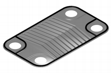
An individual plate for a heat exchanger
The plate oestrus exchanger (PHE) is a specialized blueprint well suited to transferring oestrus betwixt medium- and low-pressure fluids. Welded, semi-welded and brazed heat exchangers are used for heat exchange between high-pressure fluids or where a more than compact product is required. In identify of a pipage passing through a sleeping room, there are instead two alternate chambers, usually thin in depth, separated at their largest surface by a corrugated metal plate. The plates used in a plate and frame heat exchanger are obtained by i piece pressing of metal plates. Stainless steel is a commonly used metal for the plates because of its power to withstand loftier temperatures, its strength, and its corrosion resistance.
The plates are often spaced by condom sealing gaskets which are cemented into a section around the border of the plates. The plates are pressed to form troughs at right angles to the direction of flow of the liquid which runs through the channels in the heat exchanger. These troughs are arranged and then that they interlink with the other plates which forms the channel with gaps of one.3–1.5 mm between the plates. The plates are compressed together in a rigid frame to form an arrangement of parallel flow channels with alternating hot and cold fluids. The plates produce an extremely large surface expanse, which allows for the fastest possible transfer. Making each sleeping room sparse ensures that the majority of the volume of the liquid contacts the plate, over again aiding exchange. The troughs as well create and maintain a turbulent flow in the liquid to maximize heat transfer in the exchanger. A high degree of turbulence can be obtained at low flow rates and high estrus transfer coefficient can and then be achieved.
As compared to shell and tube heat exchangers, the temperature approach in a plate heat exchangers may be every bit depression as 1 °C whereas shell and tube heat exchangers require an approach of 5 °C or more. For the aforementioned amount of rut exchanged, the size of the plate oestrus exchanger is smaller, considering of the large heat transfer area afforded by the plates (the big area through which estrus tin can travel). Increase and reduction of the heat transfer area is unproblematic in a plate estrus-exchanger, through the addition or removal of plates from the stack.
Evaluating plate heat exchangers [edit]
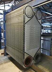
Partially dismantled exchanger, with visible plates and gaskets
All plate oestrus exchangers look similar on the exterior. The difference lies on the inside, in the details of the plate pattern and the sealing technologies used. Hence, when evaluating a plate heat exchanger, it is very of import not merely to explore the details of the product being supplied but as well to analyze the level of research and development carried out by the manufacturer and the postal service-commissioning service and spare parts availability.
An important aspect to take into account when evaluating a heat exchanger are the forms of corrugation inside the heat exchanger. At that place are two types: intermating and chevron corrugations. In full general, greater oestrus transfer enhancement is produced from chevrons for a given increase in pressure drop and are more commonly used than intermating corrugations.[2] There are and so many different ways of modifications to increase estrus exchangers efficiency that it is extremely doubtful that whatever of them will be supported by a commercial simulator. In addition, some proprietary information can never be released from the heat transfer enhancement manufacturers. However, it does not mean that any of the pre-measurements for emerging engineering are not accomplish by the engineers. Context data on several different forms of changes to oestrus exchangers is given below. The master objective of having a cost benefit heat exchanger compared to the usage of a traditional rut exchanger must always be fulfilled past heat exchanger enhancement. Fouling chapters, reliability and safety are other considerations that should be tackled.
First is Periodic Cleaning. Periodic cleaning (on-site cleaning) is the most efficient method to affluent out all the waste and dirt that over time decreases the efficiency of the heat exchanger. This approach requires both sides of the PHE (Plate Heat Exchanger) to be drained, followed by its isolation from the fluid in the arrangement. From both sides, water should be flushed out until information technology runs completely articulate. The flushing should exist carried out in the opposite direction to regular operations for the best results. Once it is washed, information technology is so time to use a circular pump and a solution tank to pass on a cleaning amanuensis while ensuring that the amanuensis is compatible with the PHE (Plate Oestrus Exchanger) gaskets and plates. Lastly, until the belch stream runs articulate, the organization should exist flushed with water again
Optimization of Plate Oestrus Exchangers [edit]
To attain improvement in PHE's, two important factors namely amount of heat transfer and pressure drop take to exist considered such that amount of rut transfer needs to be increased and pressure drops need to be decreased. In plate estrus exchangers due to presence of corrugated plate, in that location is a pregnant resistance to catamenia with high friction loss. Thus to design plate heat exchangers, ane should consider both factors.
For various range of Reynolds numbers, many correlations and chevron angles for plate heat exchangers exist. The plate geometry is ane of the most of import factor in heat transfer and pressure drop in plate heat exchangers, however such a feature is non accurately prescribed. In the corrugated plate estrus exchangers, because of narrow path betwixt the plates, there is a large pressure level chapters and the flow becomes turbulent along the path. Therefore, it requires more pumping power than the other types of rut exchangers. Therefore, higher oestrus transfer and less pressure drop are targeted. The shape of plate heat exchanger is very important for industrial applications that are affected by pressure drop.[ citation needed ]
Flow distribution and heat transfer equation [edit]
Pattern calculations of a plate heat exchanger include flow distribution and pressure driblet and heat transfer. The former is an issue of Flow distribution in manifolds.[3] A layout configuration of plate estrus exchanger tin be ordinarily simplified into a manifold system with two manifold headers for dividing and combining fluids, which can be categorized into U-type and Z-type arrangement according to menstruation direction in the headers, every bit shown in manifold arrangement. Bassiouny and Martin adult the previous theory of design.[iv] [5] In recent years Wang [6] [7] unified all the principal existing models and developed a near completed theory and design tool.
The total charge per unit of rut transfer between the hot and common cold fluids passing through a plate heat exchanger may be expressed as: Q = UA∆Tm where U is the Overall heat transfer coefficient, A is the total plate expanse, and ∆Tm is the Log hateful temperature difference. U is dependent upon the heat transfer coefficients in the hot and cold streams.[2]

Manifold organization for flow distribution
These cleaning helps to avoid fouling and scaling without the heat exchanger needing to be close downwardly or operations disrupted. In club to avert heat exchanger performance to decrease and service life of the tube extension, the OnC (Online Cleaning) can be used as a standalone approach or in conjunction with chemic treatment. The re-circulating brawl type arrangement and the castor and basket system are some of OnC techniques. OfC (Offline Cleaning) is another constructive cleaning method that finer increases the performance of heat exchangers and decreases operating expenses. This method, likewise known as pigging, uses a shape like bullet device that is inserted in each tube and using high air force per unit area to strength downward the tube. Chemical washing, hydro-diggings and hydro-lancing are other widely used methods other than OfC. Both these techniques, when used frequently, will restore the exchanger into its optimum efficiency until the fouling and scaling begin to skid slowly and adversely affecting the efficiency of the heat exchanger.
Operation and maintenance cost is necessary for a estrus exchanger. Just there are difference ways to minimize the price. Firstly, cost tin can exist minimized by reducing fouling germination on heat exchanger that decreases the overall heat transfer coefficient. According to analysis estimated, effect of fouling formation will generate a huge cost of operational losses which more than 4 billion dollars. The full fouling cost including capital letter cost, free energy cost, maintenance cost and cost of profit loss. Chemical fouling inhibitors is i of the fouling control method. For example, acrylic acrid/hydroxypropyl acrylate (AA/HPA) and acrylic acid/sulfonic acrid (AA/SA) copolymers can be used to inhibit the fouling past degradation of calcium phosphate. Adjacent, deposition of fouling can also exist reduced by installing the heat exchanger vertically as the gravitational force pulls any of the particles away from the heat transfer surface in the heat exchanger. Second, performance toll can be minimized when saturated steam is used compared to superheated steam as a fluid. Superheated steam acts as an insulator and poor estrus conductor, it is not suitable for estrus application such as oestrus exchanger
See likewise [edit]
- Plate fin heat exchanger
- Heat transfer
- LMTD
References [edit]
- ^ "Plate Heat Exchangers". Techtrans Engineers. 19 February 2022.
- ^ a b Hewitt, G (1994). Process Heat Transfer. CRC Press.
- ^ Wang, J.Y. (2011). "Theory of menstruum distribution in manifolds". Chemical Applied science J. 168 (three): 1331–1345. doi:10.1016/j.cej.2011.02.050.
- ^ Bassiouny, M.K.; Martin, H. (1984). "Catamenia distribution and pressure level drop in plate heat exchanges. Part I. U-Type system". Chem. Eng. Sci. 39 (4): 693–700. doi:10.1016/0009-2509(84)80176-one.
- ^ Bassiouny, 1000.Yard.; Martin, H. (1984). "Flow distribution and pressure drop in plate heat exchanges. Role 2. Z-Type system". Chem. Eng. Sci. 39 (4): 701–704. doi:10.1016/0009-2509(84)80177-iii.
- ^ Wang, J.Y. (2008). "Force per unit area drop and flow distribution in parallel-aqueduct of configurations of fuel jail cell stacks: U-type arrangement". International Journal of Hydrogen Free energy. 33 (21): 6339–6350. doi:x.1016/j.ijhydene.2008.08.020.
- ^ Wang, J.Y. (2010). "Pressure drop and flow distribution in parallel-channel of configurations of fuel cell stacks: Z-type arrangement". International Journal of Hydrogen Energy. 35 (11): 5498–5509. doi:ten.1016/j.ijhydene.2010.02.131.
Bibliography [edit]
- Sadik Kakac and Hongtan Liu (March 2002). Heat Exchangers: Choice, Rating and Thermal Design (2nd ed.). CRC Press. ISBN978-0-8493-0902-1.
- T. Kuppan (February 2000). Oestrus Exchanger Design Handbook (1st ed.). CRC Press. ISBN978-0-8247-9787-4.
- J. 1000. Coulson and J. F. Richardson (1999). Coulson & Richarson's Chemic Engineering science Book i (6th ed.). Butterworth Heinemann. ISBN978-0-7506-4444-0.
External links [edit]
- Heat Exchangers at Curlie
- A list of published articles pertaining to plate rut exchangers
- A screening method for the optimal selection of plate heat exchanger configurations by J.1000.Pinto and J.A.W.Gut, Academy of São Paulo, Brazil.
- Seeking the optimal design of a typical plate heat exchanger (PHE) by Athanasios G. Kanaris, Aikaterini A. Mouza and Spiros V. Paras, Aristotle University of Thessaloniki.

Source: https://en.wikipedia.org/wiki/Plate_heat_exchanger
Posted by: ishmaelnowerever98.blogspot.com
0 Response to "How To Clean Plate And Frame Heat Exchanger"
Post a Comment